how to make a AC 300v digital volt meter kit at home Circuit Diagram Section 1: Understanding the Basics of a Digital Voltmeter Circuit. A digital voltmeter circuit is an essential tool for measuring voltage in electronic circuits. This section will provide an overview of the basic components and principles involved in building a digital voltmeter circuit. 1. Analog-to-Digital Converter (ADC) The heart of a Working of digital voltmeter circuit. Step 1: Transformer steps down the input AC voltage. Step 2: The voltage divider circuit ensures a voltage less than 5 v across the 4.7k resistor and hence maximum input a.c volts as already seen in the simulation must be 311 r.m.s volts. Building digital voltmeter circuit Parts you will needs. IC1: ICL7017 IC2: CD4049, CMOS Hex Inverting Buffer/Converter D1, D2: 1N4148,75V 150mA Diodes ZD1: 2.4V 0.5W Zener diode 0.25W Resistors tolerance: 1% R1: 10K R2: 47K R3: 100K R4: 1M. VR1: 2K to 5K Trimmer Potentiometer. See modifying Digital 50V voltmeter. Capacitors

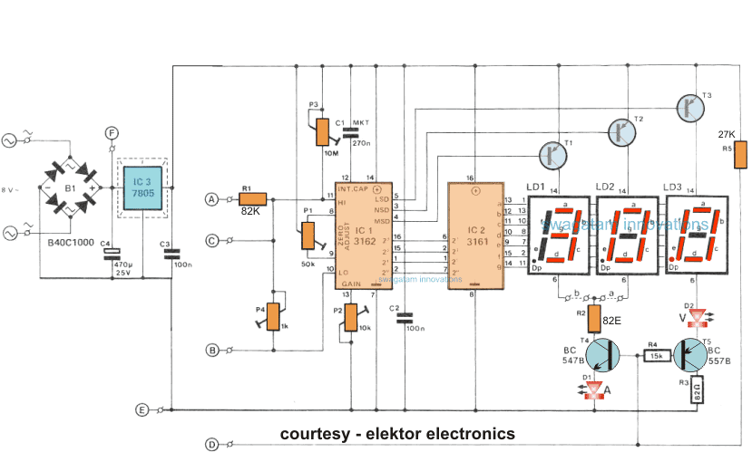
The transistors are BC640, however you may try other transistors like 8550 or 187 etc. The proposed digital voltmeter, ammeter circuit module can be effectively used with a power supply for indicating the voltage and current consumption by the connected load through the attached modules. Referring to the circuit diagram below, the 3 digit digital display module is build through the ICs CA 3162

How To Build Your Own Digital Voltmeter with Arduino? Circuit Diagram
After the end of this article, we will collectively build a digital voltmeter circuit that will ultimately make it cost-effective and precise. However, an ICL7107 is a 3.5 digit ADC converter analog to digital, which devours low power.
It's easy to make a simple digital voltmeter using an Arduino and 16x2 liquid crystal display (LCD). It's relatively simple to use an Arduino to measure voltages. The Arduino has several analog input pins that connect to an analog-to-digital converter (ADC) inside the Arduino. In order to read higher voltages, try a voltage divider circuit Figure 1 - Arduino Digital Voltmeter Circuit Diagram Figure 2 - Arduino Digital Voltmeter Circuit Diagram Components. Arduino UNO 16 x 2 The components required and the construction of the project is very simple. The working of the project is explained here. In a digital voltmeter, the voltages to be measured, which are in analog form Courtesy of All About Circuits. It's easy to make a digital voltmeter. All that's needed is an Arduino and a 16x2 liquid crystal display (LCD). Using an Arduino to measure voltages is relatively simple. Inside the Arduino, there are multiple analog input pins connecting to an analog-to-digital converter (ADC).